What are you looking for?

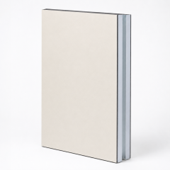

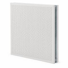

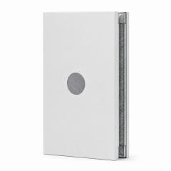
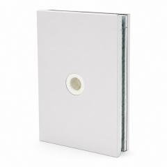


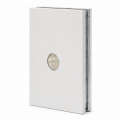

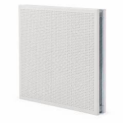
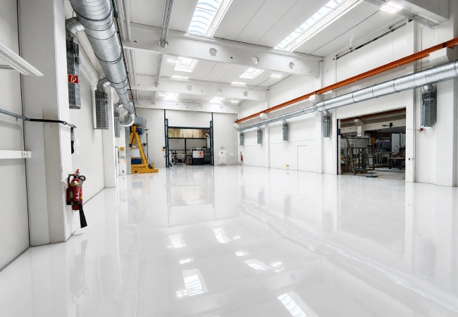
Project Case Study | Germany Cleanroom Project Germany Cleanroom Project Case Study: Wall Panel System, Export Packing, Installation Coordination and Clean Interior Finishing A cleanroom project outside the supplier's local market depends on more than panel manufacturing. This Germany project shows how Wonclean supports overseas cleanroom delivery through cleanroom wall panel supply, export packing, site installation coordination and practical finishing details for a clean interior environment. cleanroom wall panels modular cleanroom cleanroom construction The public project update for this Germany cleanroom highlighted four linked delivery stages: packed materials, overseas delivery, on-site installation coordination and clean interior finishing. The supplied project photos show the same practical sequence. Materials arrive protected. Installation teams coordinate wall panel placement and openings. The finished interior must remain clean, bright and serviceable, with wall panels, ceiling elements, ducts, doors and floor finishes working as one controlled space. Germany cleanroom project photo. Finished clean interior condition with wall panel surfaces, overhead service routes and a protected floor finish. Project Snapshot Confirmed Scope from the Project Update and Site Photos This case study is based on the LinkedIn project update and the Germany project photos supplied from Wonclean project records. It does not claim confidential customer data, final cleanliness class, room area, city, acceptance results or process details. The available information is still enough to explain the technical logic of a real overseas cleanroom delivery. Project facts used for this website case article. Item Confirmed project evidence Technical meaning Project type Germany cleanroom project with real site delivery. Requires coordination between product supply, packing, site handling, installation sequence and final interior condition. Wall system LinkedIn update identifies a cleanroom wall panel system. Wall panels form the cleanable envelope and create the alignment base for doors, windows, service openings and junctions. Packing and delivery Project update and photos show packed materials and container delivery. Export packing must protect panels, profiles, frames and accessories from deformation, moisture and site handling damage. Installation coordination Site photos show panel staging, opening coordination and local installation activity. Successful installation depends on matching drawings, numbered materials, protected floor routes and interface checks. Interior finishing Photos show a clean, bright room with wall panels, ducts, doors and finished floor surface. Cleanroom finishing must support cleaning, inspection access, service maintenance and stable operation. Delivery focus The project update emphasizes reliable products, real project support and cleaner spaces delivered. The value is in practical execution across the full overseas project path, not on...
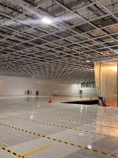
Project Case Study | Russia Semiconductor FAB 300 Russia FAB 300 Semiconductor Cleanroom Project Case Study: Ceiling Grid, Wall Panels, Raised Floor and HVAC Coordination A large-scale semiconductor cleanroom is not delivered by panels alone. In this Russia FAB 300 project, Wonclean supported the cleanroom envelope system by coordinating ceiling grid progress, cleanroom wall panel installation, raised floor planning, HVAC interfaces and practical on-site delivery details. cleanroom ceiling grid cleanroom wall panels semiconductor cleanroom The public project update for this FAB 300 cleanroom highlighted four linked workstreams: ceiling coordination, wall panel installation, raised floor planning and HVAC integration. The on-site photos show why these items cannot be treated separately. Above the clean zone, ceiling grids, ducts, suspension points and services compete for space. Around the room, wall panels and observation windows must remain aligned and cleanable. Below the process area, a dense raised floor support system must carry loads while preserving airflow and service access. Russia FAB 300 project photo. Large cleanroom construction progress showing ceiling grid work, wall panel installation and raised floor planning in one controlled space. Project Snapshot Confirmed Scope from the Project Update and Site Photos This case study uses the LinkedIn project update and the provided project photos as source material. It does not claim confidential customer data, final cleanroom classification, room area or acceptance-test results. The visible and stated scope is enough to explain the engineering logic behind a semiconductor FAB 300 cleanroom envelope. Project facts used for this website case article. Item Confirmed project evidence Technical meaning Project type Semiconductor FAB 300 cleanroom project. Requires large-area coordination between cleanroom envelope, process space and utility infrastructure. Project region Russia project photos supplied from Wonclean project records. Shows cross-border project delivery and on-site installation support requirements. Ceiling scope Visible suspended ceiling grid and overhead service coordination. Ceiling modules must coordinate with HVAC, lighting, hangers and later cleanroom commissioning access. Wall scope Cleanroom wall panel installation with integrated observation windows and service openings. Wall panels function as a cleanable envelope and as the alignment base for room interfaces. Floor scope Raised floor field with pedestal supports, conductive bonding and protected installation routes. A semiconductor cleanroom floor must combine load support, airflow planning, service access and electrostatic control details. Delivery focus LinkedIn update states Wonclean supported the cleanroom envelope system with project experience and product delivery. The value is in coordinating real site details, not only supplying individual products. Ceiling Coordination The Ceiling Grid Is a Coordination Platform...
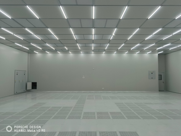
Technical Article | Cleanroom Wall System Clean Room Panel Specifications: Thickness Tolerance, Reinforcement Points and Site Acceptance Checks Clean room panel specifications should do more than name a wall panel type. They should define how the cleanroom wall system will be built, inspected and maintained: panel thickness tolerance, surface flatness, reinforcement positions, opening details, joint sealing and the acceptance checks used before handover. clean room panel specifications cleanroom wall system clean room wall systems Many cleanroom problems look like installation issues, but they begin earlier in the specification. If the drawing does not define tolerance, reinforcement and inspection requirements, the site team has to make judgment calls during installation. That is risky when the room will later carry doors, windows, pass boxes, return grilles, sockets, process utilities and ceiling interfaces. Wonclean real project photo. A corridor shows whether wall panels, doors, windows, controls and service points were coordinated before installation. Specification Scope A Useful Specification Describes the Finished Wall, Not Only the Panel Clean room wall systems include panels, profiles, sealants, doors, windows, return air grilles, ceiling connections, floor junctions and service penetrations. A narrow purchase specification may only list panel thickness and surface material. A better project specification explains how those components work together after installation. For example, a 50 mm panel and a 75 mm panel may both be suitable in a low-impact room, but the correct choice changes when the wall carries a heavy window, a pass box, a door closer or future utility openings. The clean room panel specifications should therefore identify wall zones that need backing plates, steel inserts or stronger framing. Wonclean usually treats the wall layout as a system drawing. That makes it easier to reserve reinforcement, align openings and reduce late site changes. Tolerance Thickness Tolerance and Flatness Affect Doors, Windows and Seals Panel thickness tolerance is easy to overlook because a cleanroom wall may look smooth from a distance. On site, small deviations can affect door frame alignment, window frame pressure, gasket compression, corner profile fit and the straightness of long corridors. If the wall is not flat, cleaning marks and visual waves also become more obvious under strong cleanroom lighting. The specification should state the target panel thickness, acceptable tolerance, surface flatness expectation, joint width range and inspection method. For long cleanroom corridors, it is also useful to define how alignment will be checked after the ceiling grid and floor finish are installed, not only immediately after wall panel erection. Item Specification Question Acceptance Evidence Thickness What tolerance is allowed for each panel type? Incoming material check and spot measurement. Flatness How straight must the installed wall be? V...
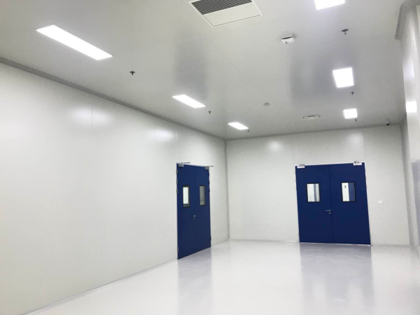
Technical Article | Cleanroom Wall Panels Fiberglass Wall Panels for Clean Zones: Moisture Resistance, Insulation and Washable Surface Design Fiberglass wall panels are often considered when a clean zone needs washable surfaces, moisture resistance and a stable enclosure without turning every room into a high-grade production cleanroom. The real design work is in the details: panel backing, insulation, joints, edges, doors, return air points and how the surface behaves after repeated cleaning. fiberglass wall panels insulated fiberglass panels clean room panel material A clean zone wall is not only a partition. It is part of the room envelope that helps control moisture, dust accumulation, cleaning recovery and service life. For electronics assembly, medical device packaging, laboratory support rooms and controlled storage areas, the right panel specification can prevent many small failures that are expensive to correct after equipment moves in. Wonclean real project photo. Wall panels, ceiling modules and floor return paths must be treated as one enclosure system, not separate decorative finishes. Material Logic Start with the Exposure, Not the Panel Name The term fiberglass wall panels can describe different constructions, from glass-fiber reinforced skins to insulated wall assemblies that use fiberglass-related materials as part of the panel build-up. Before comparing products, the project team should define what the wall will face: humidity, cleaning liquid, impact from carts, electrical service channels, pressure leakage and how often the room must be wiped down. In a dry electronics assembly area, the main concerns may be surface dusting, static behavior, dimensional stability and easy cleaning. In a wet support room, the same panel may need better edge protection, sealed penetrations and moisture-tolerant backing. In a controlled medical packaging area, the focus may shift to smoothness, low ledges, documented materials and repeatable visual inspection. This is why a clean room panel material should be specified by performance requirements instead of a single product label. Wonclean usually reviews panel surface, core, profile and project interfaces together so the final wall behaves as a maintainable cleanroom envelope. Moisture Control Moisture Resistance Depends on Edges, Joints and Penetrations Most moisture failures do not begin in the middle of a flat panel face. They begin at exposed edges, floor junctions, ceiling returns, door frames, pass-through boxes, sockets, pipe penetrations and service openings. If water or cleaning solution can migrate into those points, a panel that looks suitable on paper may lose stiffness or create hidden hygiene problems. For washable clean zones, the detail should include sealed vertical joints, compatible sealant, protected bottom edges, a coved or easy-clean base, and careful coordination with air return grilles. Where wall panels connect to ceilings, the joint must allow installation tolerance whi...
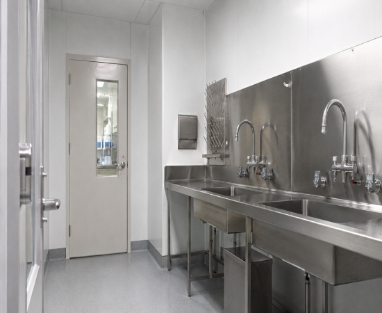
Technical Blog | Laboratory Wet Areas HPL Cleanroom Panels for Laboratory Wet Areas: Sink Walls, Reagent Rooms and Splash-Zone Detailing Laboratory wet areas expose cleanroom wall material to water, disinfectants, reagents and repeated wiping. HPL cleanroom panels can help when sink walls, reagent rooms and splash zones are detailed as part of a cleanable envelope. cleanroom wall material HPL cleanroom panel modular lab project support Wet-area cleanrooms fail quietly. A wall may look smooth on day one, but repeated splash, wiping, disinfectant exposure and reagent handling can reveal weak joints, swollen edges, stained corners or difficult-to-clean transitions. HPL cleanroom wall detailing should therefore be designed around use, not just appearance. Real product photo. HPL cleanroom panels should be evaluated by surface durability, edge closure, joint design and cleaning compatibility. Wet-Area Risk Sink Walls Are Not Ordinary Cleanroom Walls A sink wall sees local humidity, hand contact, cleaning tools and splash. If the panel edge, outlet opening, pipe penetration or countertop junction is not sealed correctly, water can enter areas that are hard to inspect. The result may be staining, swelling, hidden residue or microbial risk in spaces that operators assume are clean. A good HPL cleanroom wall detail should define the panel face, core, edge closure, sealant, corner transition, mounting method and service penetration strategy. For laboratory wet areas, it should also define how the surface will be cleaned and what chemicals are expected. ISO 14644-4 is useful because it links cleanroom requirements, design, construction and start-up. Wet-area wall details should be agreed before installation, not improvised around sinks and reagent cabinets. Real product photo. Sink walls need cleanable transitions around basins, taps, outlets and pipe penetrations. Detailing Matrix Detail Splash Zones, Reagent Rooms and Panel Joints Separately The phrase hpl cleanroom wall is too broad unless the design shows where water, disinfectant, reagents and carts will actually contact the surface. A dry corridor, a sink wall and a reagent storage room do not need the same risk controls. HPL cleanroom panel detailing for laboratory wet areas. Location Primary risk Recommended detail Sink wall Splash, pipe penetrations and trapped water. Sealed edge closure, cleanable cove and planned service penetrations. Reagent room Chemical contact, storage impact and cleaning residue. Chemical compatibility review and protected wall zones. Splash zone Repeated wiping and local moisture stress. Smooth face, compatible sealant and no exposed absorbent edge. Door and window frame Joint staining, edge swelling and cleaning shadow. Flush frame, sealed perimeter and documented inspection point. GMP Perspective Cleanable Surfaces Must Match the Contamination Control Strategy For sterile pharmaceutical facilities, EU GMP Annex 1 emphasizes contamination control strategy and cleanroom des...
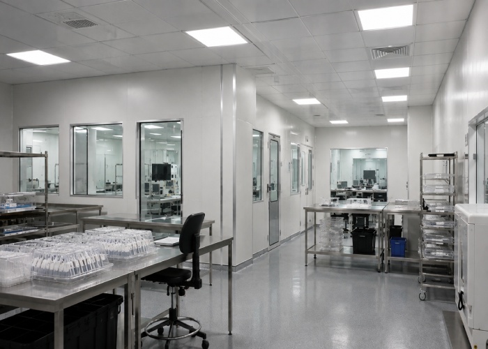
Technical Blog | Medical Device Cleanrooms Medical Lab Wall Panels for ISO 8 Device Assembly: Vision Windows, Doors and Cleanable Partitions ISO 8 medical device assembly areas need cleanroom wall panels that support repeatable cleaning, controlled personnel flow, visible supervision and stable pressure boundaries without turning doors, windows and partitions into weak points. cleanroom wall panels gmp clean room panels cleanroom doors modular cleanroom Medical lab wall panels are often specified after the process layout is already nearly fixed. That is risky. In ISO 8 device assembly, wall panels, vision windows, cleanroom doors and cleanable partitions influence how operators move, how supervisors observe the line, how materials transfer and how surfaces are cleaned after each batch or shift. Real project photo. Cleanroom corridors and room entries should keep access, cleaning and pressure relationships visible and manageable. ISO 8 Planning Start with Process Flow, Not Panel Thickness ISO 14644-1 classifies cleanrooms by airborne particle concentration. For ISO 8 device assembly, the wall panel system does not create the class by itself, but it helps protect the environment by reducing particle traps, uncontrolled leakage and cleaning blind spots. Before choosing medical lab wall panels, define the process route for components, operators, finished devices, rejects, cleaning tools and maintenance access. A wall line that looks tidy on a plan may be wrong if it forces operators to cross material routes or makes inspection windows too small for visual control. Wonclean cleanroom wall systems should therefore be coordinated with the room classification, personnel routes, door swing, observation needs, HVAC return path and pressure cascade before fabrication. Wall System Matrix Coordinate Panels, Windows and Doors as One Envelope The weakest points in a wall system are usually not the center of the panel. They are the edges: door frames, vision window frames, corner coving, ceiling junctions and service penetrations. For medical device assembly, these interfaces need flush surfaces, sealed joints and replacement logic in case a panel or frame is damaged. ISO 8 medical device assembly wall panel coordination checklist. Interface Cleanroom risk Recommended detail Panel joint Particle trap, cleaning shadow or pressure leak. Flush joint, compatible sealant and inspection record. Vision window Ledges, poor supervision or difficult cleaning. Flush glazing, sealed frame and clear observation height. Cleanroom door Pressure loss, gasket wear or traffic conflict. Smooth leaf, stable frame, gasket inspection and correct swing. Partition base Dirt accumulation at floor transition. Coved or cleanable base detail with documented seal. Real product photo. Flush vision windows support supervision and reduce protruding ledges when they are integrated with the wall panel system. Quality System View Facility Controls Should Support the Device Quality System For medi...

 Room JT30151, Building 4, Area B, No. 925 Yecheng Road, Industrial Zone, Shanghai,China
 Info@wonclean.com
Allen@wonclean.com
Joy@wonclean.com
Info@wonclean.com
Allen@wonclean.com
Joy@wonclean.com
 +86 13671979988(Allen)+86 15950938878(Joy)


 online service

