What are you looking for?

Technical Blog | Semiconductor Ceiling Coordination
In semiconductor cleanrooms, the ceiling is not a blank surface. It is a coordinated service plane where FFU grid systems, clean room ceiling panels, sprinklers, LED lighting, access hatches, cable routes and pressure boundaries all compete for space.
cleanroom ceiling system fan filter unit modular cleanroom technical consultation
A semiconductor ceiling package succeeds when it keeps the airflow layout, fire protection layout, lighting layout and maintenance layout in the same conversation. If these trades are coordinated separately, a cleanroom can pass a drawing review yet still create site conflicts above the process bay.
Ceiling Grid Logic
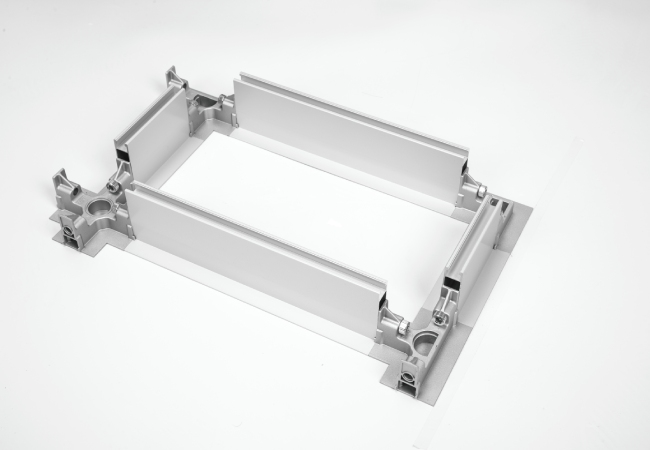
The FFU ceiling grid system should be developed from room classification targets, heat load, tool exhaust, return air paths and future service access. For high-density semiconductor areas, the grid is not only a support frame. It becomes the reference for FFUs, blank panels, filter replacement routes, lighting positions and structural hangers.
A practical coordination step is to freeze the ceiling module only after the process bay map, equipment height, maintenance clearances and airflow concept are reviewed together. Wonclean ceiling systems can be adapted for modular layouts, but the benefit is strongest when service conflicts are removed in the design stage.
ISO 14644-4 gives guidance for cleanroom design, construction and start-up, including new, modified and refurbished cleanroom installations. For a ceiling package, that means requirements should be translated into measurable coordination documents, not only layout drawings.
Trade Coordination
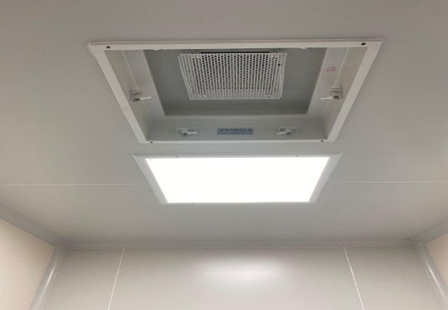
Sprinkler heads, LED lights and FFU modules often appear simple when viewed separately. The conflict appears when the final ceiling plane must preserve air distribution, fire coverage, visual comfort and serviceability at the same time. A sprinkler too close to an FFU face can interfere with maintenance. A light row placed without filter access planning can force awkward service work. An access hatch without clearance above it becomes decorative rather than useful.
| Ceiling item | Main risk | Coordination response |
|---|---|---|
| FFU modules | Uneven airflow, inaccessible filters or electrical congestion. | Reserve service zones, power drops and replacement clearance. |
| Sprinkler heads | Field relocation, ceiling penetrations or fire review delay. | Coordinate early with code consultant and approved sprinkler layout. |
| Lighting | Glare, shadowing and conflict with filter modules. | Align lights with work zones and ceiling grid service access. |
| Access hatches | No practical reach to dampers, wiring or sensors. | Map what each hatch is meant to service before fabrication. |
Panels and Hatches
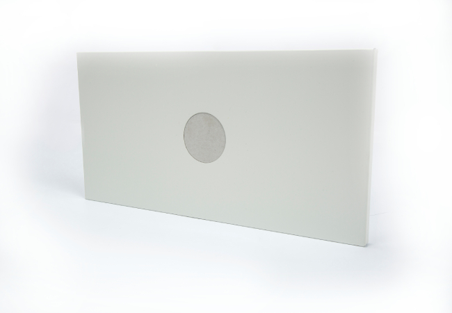
Cleanroom false ceiling panels may look interchangeable, but each panel position can carry a different function: blank closure, filter support, light integration, access hatch, sensor opening or service penetration. If the ceiling schedule does not identify these functions, installers may make field decisions that weaken cleanability or delay qualification.
For semiconductor fabs, the panel schedule should include panel type, grid size, load assumption, gasket or seal approach, adjacent services and inspection points. A factory-prepared access panel is easier to document than a later field opening, especially when it sits above a tool bay that will be difficult to enter after equipment installation.
NFPA 13 is commonly referenced for automatic sprinkler system design and installation. Cleanroom ceiling coordination should always be reviewed with the local authority, fire protection engineer and project code basis because sprinkler requirements cannot be solved by cleanroom suppliers alone.
Qualification View
ISO 14644-3 covers cleanroom performance test methods such as airflow, pressure difference, recovery and filter-related testing. A ceiling layout that is hard to access is also hard to test, troubleshoot and maintain.
Before releasing the ceiling package, check whether test locations, filter leakage access, balancing devices, pressure sensors and room recovery expectations are compatible with the actual ceiling arrangement. The goal is not to add complexity; it is to make the installed ceiling understandable to the team that has to qualify it.
Technical Fact Check
Referenced Technical Standards
FAQ
It is a ceiling support and coordination system for fan filter units, panels and service elements. In semiconductor projects it also helps organize maintenance access, lighting and service routing.
Some panels can be changed, but late changes can affect seals, airflow, sprinkler layout and commissioning records. Critical openings should be planned before fabrication.
Sprinklers are required by the applicable fire code basis. The engineering task is to coordinate their location with the cleanroom ceiling grid and avoid unnecessary field conflicts.
Access hatches let technicians inspect and service valves, dampers, wiring and sensors without uncontrolled ceiling damage. They should be linked to specific service points.

 Room JT30151, Building 4, Area B, No. 925 Yecheng Road, Industrial Zone, Shanghai,China
 Info@wonclean.com
Allen@wonclean.com
Joy@wonclean.com
Info@wonclean.com
Allen@wonclean.com
Joy@wonclean.com
 +86 13671979988(Allen)+86 15950938878(Joy)


 online service

