What are you looking for?

Technical Analysis | Semiconductor Cleanroom Ceilings
In a semiconductor cleanroom, the ceiling is the air delivery platform, service layer and structural interface for FFUs, filters, lighting, access panels and monitoring points. A T-bar ceiling system must therefore be selected around ISO cleanliness targets, FFU coverage, leakage control and maintenance access, not only profile dimensions.
T-bar ceiling cleanroom ceiling FFU ceiling fan filter unit
| GridCarry FFUs, lights, panels and access loads. | CoverageMatch airflow pattern to ISO class and heat load. | SealControl bypass leakage at filters and ceiling joints. | ServiceEnable safe filter, FFU, cable and lighting maintenance. |
The wrong ceiling choice can make a cleanroom expensive to qualify and painful to maintain. FFU density may look sufficient on a plan, but if the ceiling grid deflects, filters are difficult to change, gasket details leak or returns are poorly placed, the room may struggle to meet ISO classification and recovery expectations.
Selection Logic
ISO 14644-1 defines airborne particle cleanliness classes, but it does not prescribe a single ceiling construction. The ceiling designer must translate the target class into air supply strategy, filter location, return-air path, recovery expectation and maintenance access.
For semiconductor rooms, ceiling design should also account for tool heat, equipment height, process sensitivity, AMC strategy, static-control needs and above-ceiling service traffic. A ceiling that works for a small metrology lab may be inadequate for a dense process bay with frequent filter service and strict pressure control.
FFU Coverage
FFU coverage is often discussed as a percentage of ceiling area, but the useful question is whether clean air reaches the risk locations and returns without short-circuiting. A high coverage number can still perform poorly if FFUs are clustered away from tools, blocked by equipment, mixed with poorly sealed blank panels or not balanced with returns.
The project team should define air velocity targets, filter module size, control zones, redundancy, energy strategy and filter replacement sequence. For particle-sensitive semiconductor spaces, HEPA or ULPA filter class and documentation should be aligned with a recognized filter framework such as ISO 29463-1.
| Decision | Why it matters | Practical check |
|---|---|---|
| FFU density | Controls supply volume, recovery and local cleanliness. | Compare risk areas, heat load and return geometry. |
| Grid load rating | Prevents deflection and seal stress around filter modules. | Verify FFU, filter, lighting and access loads. |
| Blank panels and lights | Can disturb airflow or create leakage paths. | Coordinate panel schedule with airflow simulation or risk review. |
| Service access | Filter changes can become contamination events. | Define room-side or service-side replacement route. |
T-Bar System
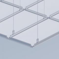
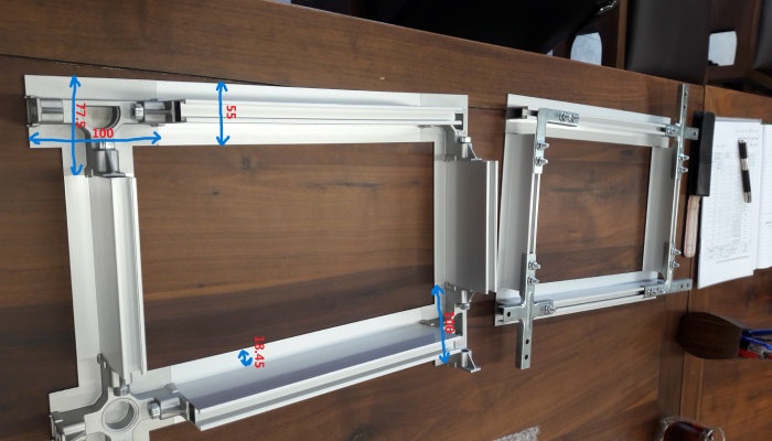
A T-bar ceiling grid for cleanrooms should provide repeatable module dimensions, rigid support, cleanable surfaces and gasket-compatible seats for FFUs and blank panels. Aluminium systems are widely used because they combine lightweight construction with corrosion resistance, but the connection details, suspension spacing and leveling method determine whether the grid remains stable during installation and maintenance.
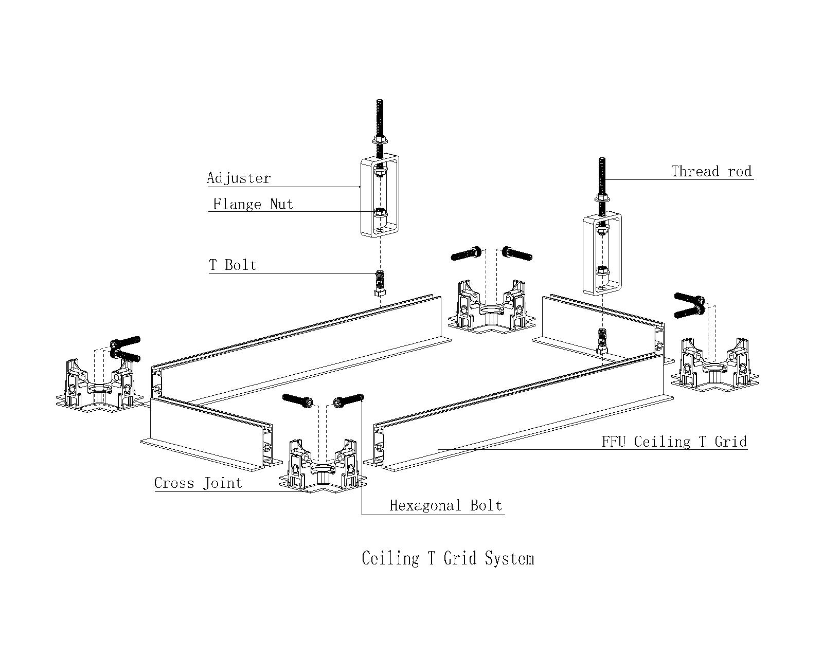
The ceiling should be reviewed as a complete assembly: grid profiles, cross connectors, suspension rods, M10 regulators or leveling components, wall interfaces, sealants, filter gaskets, lights, blank panels and access panels. If one component is changed late, airflow and leakage performance can change with it.
Qualification
ISO 14644-3 provides cleanroom test methods in support of operation and classification. For a ceiling system, practical verification may include installed filter leakage, airflow volume or velocity, air pressure difference, airflow direction visualization, recovery and particle concentration testing.
The ceiling supplier should therefore support drawings, module schedules, filter records, grid load information, installation inspection forms and maintenance guidance. These documents help the commissioning team verify that the room performs as designed rather than merely looks complete.
Energy and Operation
More FFUs are not always the best answer. Semiconductor cleanrooms need enough airflow to meet cleanliness and recovery requirements, but excessive airflow increases fan energy, noise, filter loading and thermal management challenges. Grouping FFUs into control zones can support operating flexibility, provided that airflow balance and pressure cascade remain stable.
ISO 14644-16 addresses energy efficiency in cleanrooms and associated controlled environments. In practical ceiling selection, this supports a design process where cleanroom performance and energy use are considered together: correct FFU density, efficient motors, clean filters, balanced returns and clear maintenance intervals.
Technical Fact Check
| Fact used | Source | Design implication |
|---|---|---|
| Cleanroom ISO classes are based on airborne particle concentration. | ISO 14644-1 | Ceiling and FFU design must support the required particle class. |
| Cleanroom test methods include airflow, pressure difference, recovery and filter leakage checks. | ISO 14644-3 | Ceiling layout should be designed for verification, not only installation. |
| High-efficiency air filters are classified by performance, testing and marking. | ISO 29463-1 | FFU/filter selection should include documented filter class and leakage control. |
| Cleanroom energy efficiency should be considered as part of cleanroom operation. | ISO 14644-16 | FFU coverage should balance cleanliness, recovery, pressure and fan energy. |
Referenced Standards
FAQ
Wonclean cleanroom ceiling systems combine T-bar grids, FFU support, cleanroom panels, lighting coordination and service access so semiconductor projects can move from design intent to verified ISO cleanliness with fewer ceiling conflicts.

 Room JT30151, Building 4, Area B, No. 925 Yecheng Road, Industrial Zone, Shanghai,China
 Info@wonclean.com
Allen@wonclean.com
Joy@wonclean.com
Info@wonclean.com
Allen@wonclean.com
Joy@wonclean.com
 +86 13671979988(Allen)+86 15950938878(Joy)


 online service

